Cable Tray Roll Forming Machine
Customized Cable Tray Roll Forming Machine
A cable tray line configured to your catalogue: 1.5–2.5 mm coil, 19 forming stations, servo feeding, press punching and a 22 kW main motor. Built where a standard tray line does not match the perforation, the width range or the flange detail you sell.
- Sheet thickness 1.5–2.5 mm
- Forming stations 19
- Forming speed 0–15 m/min
- Main motor 22 kW
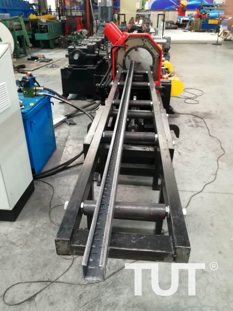
Applications & material
What this machine is built to produce
The same frame serves different buyers depending on the profile and the material grade. Start from the application closest to your project, then check the section sizes below.
Where it is used
- Heavy-duty cable tray for power plants, substations and industrial plants.
- Tray catalogues with non-standard widths, flange heights or hole patterns.
- Plants producing tray and support channel on the same floor.
Suitable material
- Hot-dip galvanised steel
- 1.5–2.5 mm
- Prepainted steel
- 1.5–2.5 mm
- Electro-galvanised steel
- 1.5–2.5 mm
- Stainless steel (special build)
- 1.5–2.0 mm
Target profiles
- Cable tray, width 100–600 mm
- Tray with a deep return flange
- Tray with a centre divider
- Perforation or slotted pattern per drawing
Not on the list? The rolls are cut to a drawing — send yours and we will confirm feasibility.
Technical data
Customized Cable Tray Roll Forming Machine specifications
Values below are for the standard build of this model. Thickness range, station count and motor rating are re-calculated when the profile or the steel grade changes.
Send your profile drawing| Parameter | Value |
|---|---|
| Sheet thickness | 1.5–2.5 mm |
| Forming stations | 19 |
| Forming speed | 0–15 m/min |
| Shaft diameter | φ75 mm, 40Cr |
| Roller material | GCr15 |
| Main motor | 22 kW |
| Hydraulic station power | 7.5 kW |
| Punching | Press punching via servo feeder |
| Cutting blade | Cr12MoV, HRC 56–58 |
| Control | PLC + touch screen |
Final values follow the profile drawing and material grade. Tolerance, power supply and line layout are confirmed on the approved drawing.
Working process
From coil to finished profile
The sequence below is the standard layout for this model. Stations are added or removed when the section needs more forming passes.
- 01 Decoiling Decoiler sized to your coil weight and ID.
- 02 Leveling Leveler ahead of the feeder.
- 03 Servo feeding Servo feed indexes the strip by pitch, so hole spacing is set numerically.
- 04 Press punching Press punches the perforation pattern.
- 05 Main roll forming 19 stations form the tray section and return flange.
- 06 Cut to length Hydraulic post-cut.
- 07 Run-out table Finished tray to the packing area.
Main components
- Main roll forming machine 19 stations, φ75 mm 40Cr shafts, GCr15 rolls.
- Servo feeder Numerical pitch control for the perforation spacing.
- Press punching station Press and die for the tray perforation pattern.
- Hydraulic cutting device Post-cut with a tray-shaped die.
- PLC control cabinet Recipes for width, pitch and length.
- Hydraulic station 7.5 kW unit.
Optional configuration
Samples & running line
Profiles from this machine, and the line in motion
Every line is sampled before shipment. Photos below are from the build of this model; the video shows the line running on production material.
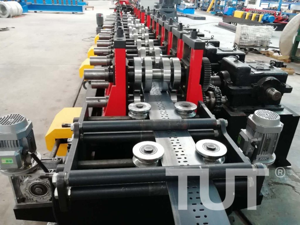
Samples are supplied at two widths and both material thicknesses, with the perforation open area and flange dimensions recorded on the inspection sheet.
Video on request
Ask for the latest running video
We record a fresh clip of this model before shipment. Ask for it and we will send the current video, plus a live call from the factory floor if you want to see the line under power.
Profile range
- Cable tray, width 100–600 mm
- Tray with a deep return flange
- Tray with a centre divider
- Perforation or slotted pattern per drawing
Engineering & service
Custom build, installation and after-sales
A roll forming line is only finished when it runs on your material at your output. These three parts of the scope are quoted together with the machine.
Custom engineering
This line exists for catalogues that do not fit a standard machine: a 2.5 mm tray for a power station order, a flange detail that carries the load, or a perforation pattern with a specific open area. Send the tray drawing and the load table, and the station count and motor rating follow from them.
- Tooling cut to your drawing or sample
- Electrics to your plant voltage and frequency
- Layout and foundation drawing before shipment
Installation & training
An engineer supervises installation and trains your operators on the actual line — not on a generic manual. Training covers coil loading, size change, tooling change and daily maintenance.
- On-site commissioning and first production run
- Operator training on your material
- Remote video support if travel is not practical
After-sales support
A 12-month warranty on the mechanical parts, with a 24-hour response on technical enquiries. Wearing parts — rollers, punch dies, hydraulic seals — are kept in stock for fast dispatch.
- 12-month mechanical warranty
- Spare rollers and dies from stock
- 24-hour response on remote support
What we need from you
Four inputs that decide 80% of the design
- 01 Profile drawing with dimensions and tolerances
- 02 Material type, thickness range and steel grade
- 03 Target output per shift or per day
- 04 Plant voltage, frequency and available floor length
Customer cases
This machine in production
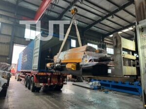
Delivery records for this machine family — the country it went to, the section it produces and the year it shipped. Each project page carries the order specification and the factory test run.
FAQ
Questions buyers ask about this machine
Answers come from real quotation discussions on this model. If your question is not here, ask it in the form below and an engineer will answer it directly.
Why does this line cost more than a light tray line?
It is built for 1.5–2.5 mm coil instead of 1.2–2.0 mm: bigger shafts, a 22 kW motor, a heavier punch and a stronger cut-off. The extra steel is what carries the load of a power station tray.
Can the perforation pattern be changed later?
Yes. The punch die is a separate part — a second die changes the pattern without touching the forming rolls. Lead time for an extra die is about 20 days.
Does it produce tray covers?
On request, as a second forming pass. Covers need their own roll set and a different run-out path, so it is quoted as an option rather than included.
What is the delivery time?
60–75 days after drawing and punch die approval.
Related equipment
Other machines in this range
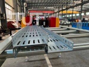
Fully Automatic Cable Tray Roll Forming Machine
Fully Automatic Cable Tray Roll Forming Machine is designed to produce perforated cable tray product, which is used to protect…
View Details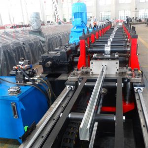
Solar Strut Channel Roll Forming Machine
Solar Strut Channel Roll Forming Machine is designed to produce solar strut with thickness from 2.0mm to 3.0mm, dimension size…
View Details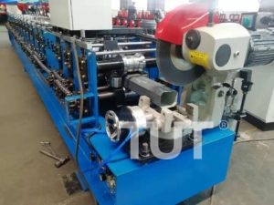
Downspout Gutter Roll Forming Machine
Downspout Gutter Roll Forming Machine is designed to produce rain downspout gutter which are vertical pipes that are used to…
View DetailsRequest a quotation
Tell us the profile, we will configure the line
Send the drawing, the material and the output you need. You get a line configuration, tooling scope and delivery schedule — usually within one working day.
- Reply within one working day
- Quotation itemised by machine, tooling and options
- Engineering review of your profile before pricing